
For those who want to read the whole story from the beginning, here are Part 1 and Part 2.
I haven’t talked about this project for a while but I was still working on it. So, what took me so long that I didn’t write about it?
Well, as I told you in Part 1, my final goal is to be able to control the robot vacuum with a GoodFET and a transceiver. The robot relies on an A7105 transceiver which is not directly supported by the GoodFET project and I don’t want to add support for it as I have already written code to support a Chipcon CC2500 transceiver that might be radio-compatible with the Avantcom one.
Knowing all the parameters we need by spying the configuration phase on the SPI bus from the remote control should have been enough to build another remote. But sometimes things don’t go well!
First, let’s talk about the good point. In the previous part, I made an assumption about the last byte of the packets being a kind of checksum and I was totally right about that! The algorithm is the easiest you can think of: sum all the bytes from the packet together and keep the least significant byte of the result as the checksum.
Now, let’s go through the things that went wrong… Just relying on the code I wrote on the GoodFET project I wasn’t able to send/receive any packet to/from the vacuum/remote. Debugging is not easy because we are talking about radio. It’s not something you can see and a lot of things can disturb the transmission as I am not living in a Faraday cage. Not being 100% sure of my code, I decided to buy the Chipcon debugger along with a CC2511DK dongle to help me on that part.

I could have tried to use rfCat for that stuff but it is only compatible with dongles that handle frequency lower than 1 GHz.
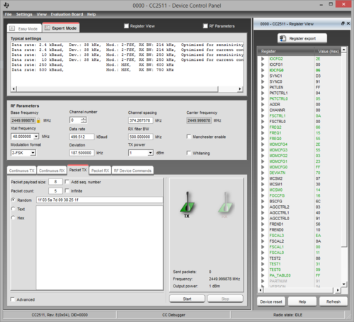
Chipcon debugger is a small device that Texas Instrument SmartRF Studio software can handle directly. This way I know for sure the TX/RX are fine and all I have to care about is the RF configuration. The main drawback of such setup is that it only runs under Windows and you have to write packets in the GUI then click the send button. In other words, I won’t be able to send 4 “Button pressed” packets followed by a “Button released” packet with good timings.
Here is a picture of the nice GUI that SmartRF Studio gives you:
Long story short of what happened:

The robot never issued a single beep to acknowledge the packets I was sending.
So, what can you do when easy options are out? Well, take the long path of course. And that involves slightly more expensive gears: SDR (Software Defined Radio). If you don’t know what SDRs are, those are radio transceivers that are re-configurable: instead of doing things in the hardware, you just setup a local oscillator frequency and a bandwidth to listen to and it will provide samples to your computer. All the signal processing is then done using the computational power of your computer (filtering, demodulating, etc.). Sorry for those who are expecting lot of details on that topic but there’s just too many things to say on that subject to fit within a couple of paragraphs. Just Google that and you will find a lot of documentation, tutorials and hacks on the Internet.
Fortunately, last year, I was one of the proud backers of the bladeRF project on Kickstarter so I already had everything needed as this board is able to do both TX and RX at the same time. Its frequency operating range goes from 300 MHz to 3 GHz so we don’t need extra electronics (an up-down converter).

For the software we will use Gnuradio 3.7 to do everything as it already provides all the required tools. For those who are not familiar with this project, Gnuradio is a very powerful tool to deal with SDR. It basically provides you simple blocks that you can arrange to do almost everything you want (yes, just like Lego blocks). Even if it is an awesome tool, there is black magic inside. Learning how to use it by yourself might not be easy despite the tutorials that you can find on the Internet. Best option at the moment is probably to wait for Michael Ossmann to release his SDR video tutorials related to his HackRF Kickstarter project or find someone that already knows how to use it (hackerspace, etc.). In my case, I was lucky enough to have worked with Arnaud, one of my team mate, that is what I am not: an electronician that learned signal processing and all that stuff. I learned a lot from him, thanks man!
The first thing to do in order to fine tune all the radio parameters is always to try to receive correctly a packet. So I built the following Gnuradio flow graph in that purpose:

GnuRadio flow graph
Let’s quickly go through the blocks I used:
- osmocom Source is the SDR reception channel. Frequency is set to 2.45 GHz with a sampling rate of 8 Msps
- Simple squelch simply provides a reception threshold. If the signal is lower than threshold, this block simply “mutes” its output. This is an easy way to get rid of the noise.
- Low pass filter is used to cleanup the signal and reduce the amount of samples (saving computational power). From the chip setup phase, we know that the bandwidth is 500 kHz so we put this as the cutoff frequency. A decimation of 8 will produce 1 Msps on the output which is enough.
- Quadrature demod is the block that will demodulate the FSK signal. Gain parameter is set to a default formula that will rely on a variable called fsk_deviation_hz. So we just have to add one block for this variable and set its value to 186000
- Rational Resampler is here to reduce once more the samplerate to fit our parameters
- Threshold will convert our signal into 0 and 1 (it just acts as a hysteresis comparator).
- Multiply const and Add const blocks just do what their name suggest. This is a simple trick to convert the output of the Threshold block (“0” and “1”) into something suitable for the next block (ie. positive and negative values, “-1” and “1”)
- Binary slicer will convert our float values into bytes
- Correlate Access Code is a pattern detector. Just give it a pattern (max. 64 bits) and it will modify your stream to mark this specific pattern. In this case, I set the access code to be the remote ID (0x58 0x52 0xD2 0x41). Threshold value is the amount of incorrect bits that can occur within the pattern.
- UChar to Float just converts data back to float because the scope cannot display bytes
- Scope Sink will provide us a neat scope to check our signal
Running the graph will pop up a GUI windows with all the controls and here is a packet that I successfully grabbed:
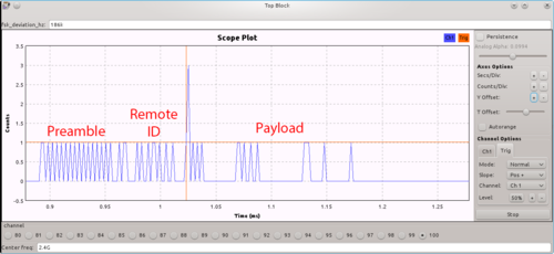
I added text to the capture in order to spot the three parts of the packet. Red lines are for the trigger configuration.
The packet starts on the left with the preamble immediately followed by the remote ID. The end of the remote ID code is tagged by the correlate access code block and this is the spike you can see on the capture. The spike value can be either 2 or 3, depending on the bit value it had altered and I used that property to trigger the scope and display a packet. The rest of the bit stream encodes the 8-byte packet that I already described in the previous part.
That’s looks promising! Reception is good! Next step is to modify this graph by adding a custom block (that I still have to write) to create packets out of this bitstream. The flow graph will then send those packets to a local UDP socket instead of the scope sink, so that we can process them easily. This will also help us for the next step: transmitting!
But that’s going to be detailed on the next part :)