
Ok, this is my first blog post, moreover in English, so be kind. I hope this stuff will be helpful to somebody :-)
Recently I was giving a try to those automated hoovering robots. iRobot Roomba really seems to be the leader in that domain but those are really expensive for a test and I could not find any discount offer on them. So I turned up to buy instead a H.koenig SWR22 that I got for less than 80 euros!

This hoover comes with several accessories, including a remote.

Whereas iRobot’s remotes seem to rely on infrared, H.koenig has choosen an RF remote operating at the 2.4 GHz ISM band. As I am trying to learn radiofrequency stuff and starts playing with Software Defined Radios (SDR) and Gnuradio I thought I would give it a try to reverse that remote and to “build” another one. And that’s what this article is about.
As the unique Crazy Aussie Dave always says:
“Don’t turn it on, take it appart!”
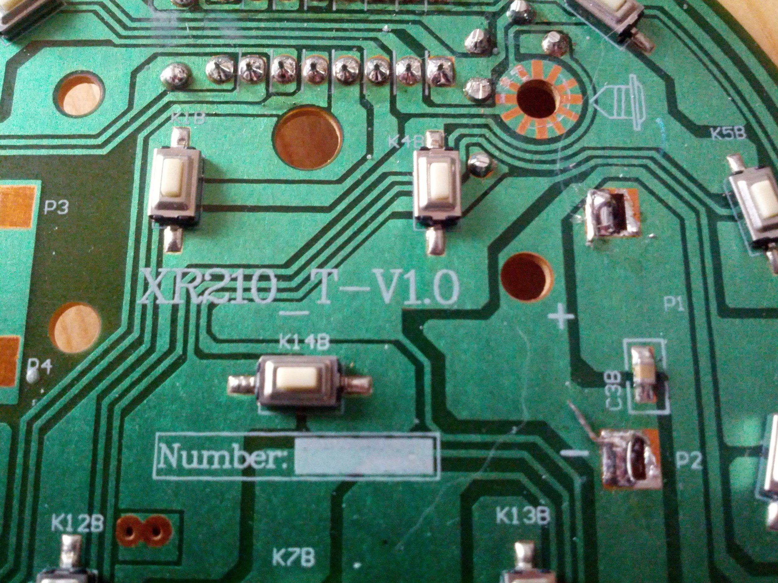
As you could expect, there is not a lot of stuff in there: 14 buttons, a microcontroller with its ceramic oscillator, passive components and an RF module probably connected with the µC with a classic SPI bus.
Just for the reference, we are dealing here with the remote “XR210_T” in its first revision. It may be compatible with other models from H.koenig.
Let’s have a closer look at the microcontroller. I do not expect its firmware to be upgradeable but if the manufacturer is kind enough, maybe we can just extract the firmware and reverse it to get all the commands. At least, as electronics is just a hobby, I am more comfortable reversing software than dealing with components :-)

It is not a really nice high quality shot but you can read the reference of this MCU: TK98P01 in a good old through-hole DIL16 package.
Unfortunately a Google search on that just gave nothing. I couldn’t find any datasheet for that one and although several links pointed to Holtek semiconductors, that reference doesn’t seem to be on their catalog.
By the way, I didn’t expect that puppy to be anything but a one-time programmable device.
So let’s forget the software approach as it seems to be helpless and let’s take a shot at the microscope to see what RF transceiver module they are using.

Close-up on the radio transceiver
Okay, that looks far more promising. This transceiver is an Avantcom A7105. This is a small RF transceiver from a Taiwanese company, operating at 2.4GHz with FSK or GFSK modulation. It is quite similar to the Nordic nRF2401 and the Texas Instrument (formerly Chipcon) CC2500. Hopefully I already played with those ones and all it requires is a classic SPI (Serial Peripheral Interface) bus.
Following traces under the microscope to identify the SPI bus signals is a bit boring and there isn’t enough pins to bother doing so. Just connecting the pins to a logic analyzer such as my Saleae Logic is enough. The software will do the job.

Regarding the picture here-above, the MCU is running at 4MHz with this little ceramic oscillator. Therefore, the SPI bus should not run above this frequency and we don’t need to use the full 24MHz bandwith of the Saleae Logic analyzer.
After wiring the logic analyzer, capturing a lot of samples for seconds and playing with several buttons during that time, I got the following capture:

If you are not familiar with the SPI bus protocol, it basically relies on 4 signals:
- MOSI (Master Out Slave In) is used to transmit data from the MCU to the transceiver;
- MISO (Master In Slave Out) is used to transmit data the other way, of course;
- SCK is the clock signal;
- SCS is an inverted input to select a chip. So when it goes low, the transmission can start.
In our case, the SCS signal is obviously the last one, on channel 7 and SCK, the clock signal, is on channel 6. But wait, only channel 5 remains and we still need two signals.
Reading the datasheet, the Avantcom A7105 is using a 3-wire SPI bus by using only one wire for both MOSI and MISO signals. That is a bit confusing at first (at least, it was for me). Moreover, whereas the A7105 uses 8 bits per transfer in Most Significant Bit (MSB) order, some strobes only requires 4 bits! That should mess a little bit the Saleae SPI decoder but writing a specific decoder for that should not be necessary.
After the SPI decoder setup, we got a hit:
As you can see, all the input is perfectly decoded. We just have to remember that some bytes are commands/data, others are answers. And the 4 bits strobes have to be decoded manually.
After that, I ran another capture while powering on the remote. This is just to be sure that I had the initial setup configuration of the transceiver. But in fact, H.koenig did a pretty weird choice in their MCU program: the transceiver is not initialized at powerup. Instead, they reset and then reconfigure the transceiver each time a button is sent on the radio! What a loss of both power and time! Imagine that each time, the transceiver has to recalibrate its local oscillator and lock its PLL. Unless someone has an explanation for that, I consider that the firmware has been developed during an internship :-)
Ok, so here comes the long and boring stuff: capturing every single button and decoding all that stuff with the A7105 datasheet.
Hopefully the setup remains the same whatever button you press. As you can see, it is a quite long setup process as they are writing almost every single register of the transceiver (yes, even the “Reserved for internal use” ones!). Like I said, intership work :)
So here it is (sorry for the layout but Tumblr prevents me from writing tables):
0x00 0x00 Reset the chip
0x06 0x58 0x52 0xD2 0x41 Write ID = 0x58 0x52 0xD2 0x41
0x46 Read the ID but /SCS is set high so they don’t care about the answer…
0x01 0x42 Write Mode Control (Auto RSSI + FIFO Mode)
0x02 0x00 Write Calc
0x03 0x08 Set packet length to 8 bytes
0x04 0x00 Write FIFO 2
0x07 0x00 Write RC OSC I
0x08 0x00 Write RC OSC II
0x09 0x00 Write RC OSC III
0x0A 0x00 Write CKO Pin
0x0B 0x01 Write GPIO1 Pin
0x0C 0x21 Write GPIO2 Pin
0x0D 0x05 Write Clock
0x0E 0x00 Write Data rate (500 kpbs)
0x0F 0x50 Write PLL I (Channel is set to 0x50 which gives a +40 MHz offset)
0x10 0x9E Write PLL II
0x11 0x4B Write PLL III
0x12 0x00 Write PLL IV
0x13 0x02 Write PLL V
0x14 0x16 Write TX I
0x15 0x2B Write TX II
0x16 0x12 Write Delay I
0x17 0x00 Write Delay II
0x18 0x22 Write RX
0x19 0x80 Write RX Gain I
0x1A 0x80 Write RX Gain II
0x1B 0x00 Write RX Gain III
0x1C 0x0E Write RX Gain IV
0x1D 0x32 Write RSSI Threshold
0x1E 0xC3 Write ADC
0x1F 0x07 Write Code I (sets Preamble length to 4 bytes)
0x20 0x16 Write Code II
0x21 0x00 Write Code III
0x22 0x00 Write IF Calibration I
0x24 0x00 Write VCO current Calibration
0x25 0x00 Write VCO Single band Calibration I
0x26 0x3A Write VCO Single band Calibration II
0x27 0x00 Write Battery detect
0x28 0x17 Write TX test
0x29 0x47 Write RX DEM test I
0x2A 0x80 Write RX DEM test II
0x2B 0x01 Write CPC
0x2C 0x05 Write Crystal test
0x2D 0x45 Write PLL test
0x2E 0x18 Write VCO test I
0x2F 0x00 Write VCO test II
0x30 0x01 Write IFAT
0x31 0x0F Write RScale
0x02 0x01 Write Calc (Enables IF Filter Bank calibration)
0x42 0x00 Read Calc (0x00 means calibration is done)
0x62 0x07 Read IF Calibration I
0x24 0x13 Write VCO current Calibration
0x25 0x09 Write VCO Single band Calibration I
Strobe 0b1010 Standby mode
Strobe 0b1110 FIFO write pointer reset (ie clears the FIFO)
0x05 [8 bytes] Write FIFO data
0x0F 0x64 Write PLL I (Sets channel to 0x64 hence Freq=2450.001 MHz)
Strobe 0b1101 TX mode
That’s all for the setup. I still don’t get why they are moving from channel 0x50 to channel 0x64 right before sending the data. They could have set the transceiver to the right channel at the beginning. Looks like poor quality code to me.
That’s all for now. Next I will detail how packets look like, what is sent over the air and the values for every single button of the remote.
I will also check if I can get things to work with a Chipcon CC2500 instead of the Avantcom A7501. This way, I may be able to get a Python remote working with a GoodFET:

The choice of the CC2500 is only driven by the fact that I already wrote the firmware for the GoodFET to support it monthes ago and I know that the TX is ok (I still have to debug and finish the RX part though).
Moreover I have another (unpublished) project relying on the CC2500 so that lets me know that chip a bit deeper :-)