
During the previous part, we were able to use GNU Radio and a Software Defined Radio (SDR) in order to receive and demodulate RF packets.
Now is the time to go a bit further: extract and decode packets and then, the counterpart, encode and send packets back.
Even though I will use my robot vacuum as an example, this blog post can be considered as a simple how-to about writing a simple packet sink in GNU Radio.
First of all, we need to modify the previous graph flow we had in GNU Radio Companion (GRC), first reason being that we were using the scope as the output and we were doing it “the ugly way”. Let me explain.
Last time we were using Rational Resampler and Threshold blocks to get a view of the bits that we were receiving, ie. we were resampling the signal exactly at its bitrate. There is a really big drawback doing this: the odds that your sampling clock is perfectly synchronised with the sender’s one are… well… not that huge as you can guess :-)
That’s why there is a magical block that will do the job for you: Clock Recovery MM. The main parameter to give to this block is expressed in “samples/symbols”, that is to say, your sampling rate (samples/seconds) divided by your target bitrate (symbols/seconds). With that figure, this block will do its black magic to recover the clock of the sender and synchronise its work with it to extract your bitstream.
So, after modification, the flow graph looks like this:
This version is more complicated but that’s because it is able to both receive and transmit frames and I am going to detail everything about it. Don’t be afraid and keep reading!
As it may not be easy to read it, click here for a full size capture.
The first new block that appear is Frequency Xlating FIR Filter. This does 3 things at once:
- It shifts your signal in the frequency domain to recenter it. GNU Radio only processes signal at the baseband level and that’s why, by default, your FFT is centered around 0 Hz. This operation is strictly equivalent, in terms of digital signal porcessing, as multiplying the signal from osmoscom Source with a generated sine wave which frequency is the offset you want.
- It decimates your signal ie. it reduces the sample rate to save CPU resources. Here, I am simply dividing the samplerate by 2 so the output of this block will be at 2 Msps.
- It filters the signal through the obscure Taps parameter. In the screenshot you only have an overview of the value but basically, I am building here, in Python, a Low Pass Filter. The filtering is applied after shifting so the goal of this filter is to isolate the signal you are interested in.
Why do we need to recenter our signal? Why not simply sniffing on the given frequency? Well, usually, SDR have a DC spike on the frequency you are tune at. This is done by construction and could not be easily circumvented. If you are used to the cheap RTL-SDR dongles, you should have never seen that spike because the output is AC coupled but the drawback is that the center frequency is unusable because a portion of the real signal has been canceled too in the process. So that’s a common thing to listen to not-so-far frequency, recenter the signal and get rid of that ugly spike with a low pass filter.
As the low pass filter is already done in the Frequency Xlating FIR Filter, the Low Pass Filter block that was right after the Simple Squelch vanished. No need to waste CPU by filtering twice.
In the previous article, between our signal demodulator (Quadrature Demod block) and the Binary Slicer block, we had 4 blocks that are replaced by 2 blocks in the latest version of the flow graph. You are already familiar with the Low Pass Filter block so I won’t explain it again. I am just doing extra filtering after demodulation to clean up the signal, nothing more.
And then we have the magical block, Clock Recovery MM. As I explained earlier, its role is to recover the clock of the sender of your signal to synchronise with it, hence its name. The only paramater you have to change in your flow graphs is the first one, Omega. I honestly don’t know what the other values stand for at the moment (I am slowly starting to learn about DSP to better understanding what I am doing) but the default values are fine.
Finally, after the Binary Slicer we have a new dedicated block that takes bytes in its input and outputs messages. Let’s forget about the last two blocks for the moment. This block, Hkoenig sink bb, is the one I wrote in C++ (mainly because I haven’t find how to do it in Python) and I will explain here the several steps I followed and how it works. It has three main tasks to do:
- Find the Access Code within the bitstream. If you look back, this part was previously done by the Correlate Access Code block. The goal here is to find the beginning of a packet with a given error tolerance
- Extract the packet. In this case, it is very simple as we are dealing with fixed size packets. All we have to do is grab the bits until we have the right amount
- Reject bad packets. Remember that we have a simple checksum byte at the packet. We are going to compare the computed checksum with the one receive through the radio and if we have a match, then we output the packet and resets our state automaton
First step is to create an GNU Radio OOB module by using the provided tool gr_modtool.
$ gr_modtool newmod jmichel
Creating out-of-tree module in ./gr-jmichel... Done.
Use 'gr_modtool add' to add a new block to this currently empty module.
Then we add a new block to this module:
$ cd gr-jmichel
$ gr_modtool add -t general hkoenig_sink_bb
GNU Radio module name identified: jmichel
Language: C++
Block/code identifier: hkoenig_sink_bb
Enter valid argument list, including default arguments: unsigned long access_addr
Add Python QA code? [Y/n] Y
Add C++ QA code? [y/N] N
Adding file 'lib/hkoenig_sink_bb_impl.h'...
Adding file 'lib/hkoenig_sink_bb_impl.cc'...
Adding file 'include/jmichel/hkoenig_sink_bb.h'...
Editing swig/jmichel_swig.i...
Adding file 'python/qa_hkoenig_bb_sink.py'...
Editing python/CMakeLists.txt...
Adding file 'grc/jmichel_hkoenig_bb_sink.xml'...
Editing grc/CMakeLists.txt...
The tool already created all the directory structure, files, building chain, etc. for us. Awesome! All we have to do is fill the gaps is some of the files.
First, lets edit lib/hkoenig_sink_impl.h:

I added several things to this class:
- send_frame() function is an internal function that will be called when a valid packet as been found
- _data_shift_reg is our internal accumulator in which we will push the bits
- _nshift just keeps track of how many bits we have pushed in the accumulator
- _frame is our packet
- the enum _state simply lists the different states of our automaton
- access_addr() and set_access_addr() are simply accessors around the private item to allow this variable to be changed while the graph is running. Otherwise, by default, everything is passed on the constructor once for all.
Lets move to the code now, in lib/hkoenig_sink_bb_impl.cc.
First, lets see the constructor:

We simply modify the input io_signature (the first one) to have exactly 1 input (hence MIN=MAX=1) of bytes (unsigned char). As there is no way to build an io_signature for messages, we simply declare that our block as no output. Then we set _data_shift_reg and _access_addr to their respective values and finally, we register an output message port named out. That will be our output.
Now lets look at our main big function, general_work():

The code is available on my Bitbucket account so, if can’t read it through the capture, just follow it there.
The general prototype of this function is able to deal with multiple inputs and multiple outputs. To make the code easier to read, the local variable in will be our single input stream.
Then, for every input item we have:
- we push the bit to our shift register
- our initial state is ACCESS_CODE and there, we XOR our current shift register value with the expected access address value. After four lines of mathematics trickery, we have the Hamming distance between those two values, that is to say we have computed the number of erroneous bits to get our access code. In the Correlate Access Code block we have used previously, this is the Threshold parameter.
- If we have at most one bit of error (the value has been extracted by spying on the SPI bus on the real remote and analyzing the configuration values with the datasheet), we are good to process the frame. So we start writing the access address (the good one, not the received one that may contain one erroneous bit) at the beginning of _frame, we change our automaton state to DATA and we reset our _data_shift_reg and _nshift counter.
Here is the end of the function:

- If we have shifted a complete byte (remember, shifting the bit is done before the switch/case statement), we append it to our _frame.
- If we have completed a frame (ie. we have pushed 8*8 bits), we move back to the ACCESS_CODE state, we reset both _data_shift_reg and _nshift and we compute the checksum against the extracted frame
- If the computed checksum matches the one seen over-the-air, we call send_frame()
- finally, at the end of the for loop, we tell the scheduler that we have processed all items by calling consume() and we always return as we don’t have a synchronous output of samples.
Now let’s have a look at send_frame():

Very simple one, compared to the automaton:
- We create an empty metadata dictionnary
- We create a message blob from the _frame
- We publish the blob and its metadata on the out message port
- We reset _frame for the next one
If you have followed me so far through all this process, we still have one file to modify: the XML file that describes our block to gnuradio-companion and that also gives him instructions on how to generate Python code for our block. Normally, all you have to do in this file is configuring the parameters of your block (those passed to the constructor) and the names/types of both inputs and outputs. But here we have an extra line to write to tell GRC that we can change a parameter while the graph is running.
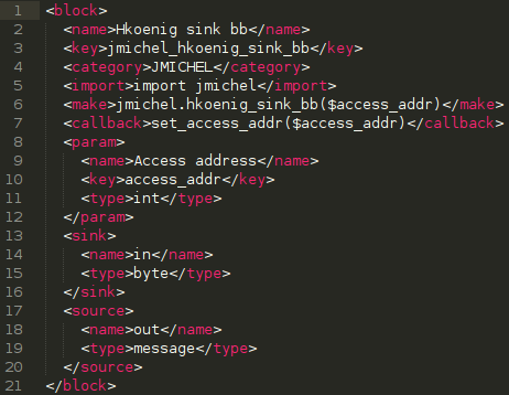
Nothing too complicated here except that the names may seem reversed for sink and source tags (in GNU Radio, a sink processes samples so it is your input whereas source produces samples so it is an output):
- name is just the display name in GRC
- key must be unique and match the corresponding parameter name in the make tag (preceded by a dollar sign)
- type must be set to a valid Python type
- our sourcetype is message
- the callback tag contains the public method to set the parameters that are given in arguments. GRC will understand that and will underline those in the GUI to inform you that they are runtime configurable.
Enough for the code, let’s go back to our flow graph to continue the explanations. But first, a small digression. On 6th August 2014, two coworkers from Airbus DS Cybersecurity and myself were presenting at BlackHat USA 2014 a new tool we wrote and that my employer has let us release as opensource software. This tool is called scapy-radio and connects together scapy for packet dissection/manipulation with GNU Radio. Basically, it replaces your usual ethernet card by a Software Defined Radio to allow radiofrequency pentesting. If you haven’t heard of that tool, I suggest you read our slides or our whitepaper because the next three blocks I am going to describe relies on that tool!
As described in our slides/whitepaper, Add GR header simply prepends the packet with our custom header that allows scapy to process it. Here, I have arbitrarily chose to use 128 as the protocol value. Conversely, Strip GR header is used on the transmission side to remove this header (we obviously don’t want to send it over-the-air). The packet with its GR header is then sent to a UDP Client socket that connects back to scapy-radio. And we are done for receiving!
Briefly, I will also explain the transmission part:
- Socket PDU UDP Server receives the packets from scapy-radio. Just note that the port is not the same as in the UDP Client socket.
- Strip GR header has already been explained previously
- Preamb prefixer bb is just another block I have written to prepend a packet with a configurable preamble. Preamble is required for the transmission to help the clock recovery system to synchronize with us but it is not part of the packet so we have to add it in GNU Radio. I won’t go into the details of its parameters here because I will describe all my custom blocks on a wiki associated with the code repository.
- PDU to Tagged Stream just extracts the blob in the message (our packet) and converts it back to a byte stream.
- Packed to Unpacked will convert our byte stream into a bit stream.
- UChar to Float will simply cast our bits (0, 1) into floats (0.0, 1.0)
- Then we use the Multiply Const and Add Const trick I already explained to recenter our values from [0.0, 1.0] to [-1.0, 1.0]
- Repeat will just duplicate each sample a given amount of times (consider that as a dumb resampler) to have the correct samplerate before modulation our bitstream
- VCO (complex) is the block that will do FSK modulation. Its name means Voltage Controled Oscillator, the voltage being the sample value on its input. Sensitivity is the frequency deviation in hertz.
- Finally we have our osmcom Sink that will send our modulated samples.
This flowgraph implements both the transmitter and the receiver. But you may wonder how to use this graph. I’ve mentioned scapy-radio and indeed we are going to use it. All you have to do is:
- Get scapy-radio and compile/install it on your system
- Get gr-jmichel and compile/install it too
- copy my flowgraph from examples/hkoenig_vacuum.grc to $HOME/.scapy/radio/
- use my Python script apps/gr-hkoenig-scapy.py
Without any argument it will sniff for packets and print them on the console. If run in interactive mode it will give you a scapy-radio shell. And you can also just pass arguments to send several buttons to the vacuum of course :)
In conclusion of this long article and for those who are patient enough to follow what was supposed to be a trilogy of blog posts to control my vacuum with a GoodFET, I now have a way to send and receive packets that are understood by the vacuum. Moreover, thanks to GNU Radio, I now have a way to debug other sender/receivers. So, hopefully, the next part of this saga is going to be about debugging my GoodFET code and send packets to that damn vacuum with a very cheap transceiver (because right now, my bladeRF is more expansive than the vacuum itself…).
As always, any questions/comments/suggestions are welcome. Just be aware that, using the link Ask me anything form on this blog may lead to the publication of both the question and my answer on this blog. Most of the time, I prefer to answer them privately but for that, you have to give me a way to answer you privately, either by not being “Anonymous” or by providing me an email in your question (it will also automatically prevents me from publishing it as I cannot edit the question and of course I don’t want to publish one’s email). So feel free to use it, even if you want me to write a blog post about something (providing I have the skills to tackle this subject.